Signal Conditioning

Signal conditioning is necessary to convert the output from a sensor into a suitable signal that can be processed or transmitted, and may include filtering, signal amplification, linearisation, or converting a signal to a particular standard analog or digital interface and protocol. Some of the typical signal conditioning options available are shown below. All signal conditioning options are fully customisable to suit each application.

RM-044

The RM-044 has been designed as a low-cost, stand-alone unit to provide signal conditioning for strain gauge type transducers such as Pressure Transducers and Load Cells. It can also be factory configured for ½ Bridge and ¼ bridge 120 ohm and 350 ohm strain gauges. Gain selection and gross offset correction and all internally link selectable. The electronics is housed in a plastic enclosure measuring 100x115x20mm. Four, 3-pin connectors are provided for signal, transducer and power connections. The RM-044 is normally supplied to provide 10 volts output for the full range of the transducer but the output will drive over the full range of ± 10 volts. The output is also configured to provide 4 to 20mA signals if required.

  • Power Supply: +24 V Nominal (18 To 30 V). (12V available with 5V excitation and +/-5V output, consult factory)
  • Transducer Excitation: +1.3 to +10 VOLT @ 50 mA max (Or ±15 Volt @ 35 mA max. link selectable)
  • Excitation Stability: 0.02 % / °C
  • Input Impedance: > 100 MW (Differential)
  • CMRR: 100 dB @ 50 Hz
  • Linearity: 0.01 %
  • Gain Range: 120 to 3200
  • Frequency Response: 20 Hz Std 4 pole (up to 20KHz available, consult factory)
  • Outputs: ± 10 V @ 5 mA Max 4 to 20 mA (500W max)
  • Output noise: 1 mV RMS
  • Environmental 0 to 70 °C 90% R.H. N/C
  • Physical: 100 x 115 x 20 mm (LWH)

The RM-044 can be factory configured for many different types of sensors. 

Some example configurations includes:

  • Differential and full bridge  – for use with load cells, pressure transducers and most strain gauges
  • Single ended – for use with transducers with high level output (i.e. 0 – 5V, or 0 – 10V)
  • Single ended ratiometric – for use with ratiometric transducers (such as inclinometers)
  • Three and two wire quarter bridge
  • Half bridge strain gauge
  • Current input (4 – 20mA)

Note: Specifications subject to change without notice

RM-074

The RM-074 operates with all known LVDTs`, providing cost effective excitation, amplification and demodulation. The output signal is compatible with PLC’s, computer input cards, data loggers and stand-alone indicators.

  • Power Supply: 24 V nom. 120mA (Operates from 18 to 30 Volt) Optional 12 V DC
  • Transducer Excitation: 2.5, 5 or 10kHz.
  • Excitation Level: 1.8 V rms.
  • LVDT Sensitivity: 12 mV/V to 4.0 V/V
  • Output: User Selectable ±10 V(5mA max.), 0-10 V (5 mA max.) and 4 to 20 mA (500 ohm maximum loop impedance)
  • Zero Adjust: ± 10
  • Volt RTO Frequency Response: DC to 250 Hz (Others on special order)
  • Phase Adjust: 0 to ±99 degree
  • Environmental: 0 to 65 °C, 90% RH non condensing
  • Thermal Stability, Combined Span and
  • Zero: < 0.01% / °C
  • Non-Linearity: < ± 0.02% FSO
  • Output Noise: < 5mV rms RTO
  • Size: 110H x 100D x 17.5W

Note: Specifications subject to change without notice

D3260C

The D3260C module has been designed as a cost effective universal module for conditioning strain gauge load cells, for level conversion and for current to voltage conversion applications.

  • Power Supply: +24 V Nom. (18 to 30 V) or ± 15 V
  • Transducer Supply: ± 15 V @ 35 mA max, +5 OR +10 V @ 50 mA max
  • Input Impedance: > 100 MW (differential)
  • CMRR: 100 dB @ 50 Hz typ.
  • Linearity: 0.01% typ.
  • Zero Stability: 0.05% / °C of F.R.O. typ.
  • Gain Stability: 0.05% / °C typ.
  • Zero Supression: ±10 Volts RTO link & trim selectable
  • Frequency Response: 20 Hz or 1 KHz, factory set
  • Outputs: ± 10 Volts @ 5 mA max, 4 to 20 mA (500W max)
  • Output Noise: 5 mV RMS with + 24 V supply typ., 1 mV RMS with ± 15 V supply typ.
  • Environment: 0 to 70 °C 90% R.H. N/C
  • Physical: 90 x 45 x 25 mm (LWH) 4 mounting points

Note: Specifications subject to change without notice

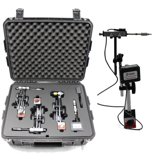
XTRAN Telemetry Measurement System (XTMS)

XTMS was designed to remove mining maintenance personnel from dangerous live work while facilitating accurate Wireless Measurement from a safe location and improving operational efficiency. The Industry refers to this as “Elimination of Live Work” or ELW, and has come about with a collaboration of AMA’s integration knowledge, and personnel in the industry performing the live work. XTMS sets the industry benchmark for functionality, scalability and flexibility. It's designed for many measurement locations and aims to remove the need for personnel to take manual measurements in live and potentially dangerous areas, especially during maintenance on heavy machinery and vehicles. The system can be configured with various sensor solutions such as Pressure, Linear Position, RPM, Temperature, Tilt, Vibration, Force, and more. It involves the use of wireless sensors that send measurement data via a 2.4GHz wireless platform directly to an integrated or USB wireless base station. Measurement data from each of the sensors can be viewed and logged and custom reports can be generated for predictive machine maintenance and trend analysis.

Sensors

Integer at faucibus urna nullam condimentum leo id elit sagittis auctor. Curabitur elementum nunc a leo imperdiet.

Communications

Integer at faucibus urna nullam condimentum leo id elit sagittis auctor. Curabitur elementum nunc a leo imperdiet.

Viewing/Logging

Integer at faucibus urna nullam condimentum leo id elit sagittis auctor. Curabitur elementum nunc a leo imperdiet.

Custom Solutions

Etiam elementum euismod commodo. Proin eleifend eget quam ut efficitur. Mauris a accumsan mauris.