Monday - Thursday 9AM - 5PM | Friday 9AM - 4PM

How Signal Conditioning Improves Sensor Accuracy

A sensor doesn’t lie, but it doesn’t always tell the truth clearly either. I’ve pulled apart enough junction boxes on mine sites to know that the raw output of a strain gauge or a pressure transducer is almost never usable on its own. It’s a few millivolts, buried under electrical noise from VSDs and switchgear, riding on a cable that can run hundreds of metres back to the control room. Somewhere between the sensor and the screen, that raw signal has to become something a PLC, data logger, or SCADA system can actually read, and that’s the job of signal conditioning.
This guide walks through what signal conditioning does, how amplification, filtering, and analog-to-digital conversion each play a part, and why skipping any of these steps quietly wrecks the accuracy of an otherwise good sensor.
What Signal Conditioning Actually Does
Signal conditioning is the set of electronic processes that take a sensor’s raw output and turn it into something usable downstream. XTRAN describes it plainly on its signal conditioning page: converting sensor outputs into suitable signals that can be processed or transmitted, which can include filtering, amplification, linearisation, and conversion to an analog or digital format.
That definition covers a lot of ground, because signal conditioning genuinely does a lot of jobs. Depending on the sensor type, it might:
- Boost a signal that’s too weak to travel or measure accurately
- Strip out electrical noise picked up along the cable run
- Convert a non-linear sensor curve into a straight-line output
- Isolate the sensor circuit from the rest of the measurement system
- Translate an analog voltage or current into a digital value a computer can log
Skip conditioning altogether, and even a well-calibrated pressure transducer or load cell will hand you numbers that drift, jump around, or simply don’t match reality.
Amplification: Making a Weak Signal Usable
Most strain-gauge based sensors, including load cells, pressure transducers, and torque sensors, output somewhere in the millivolt range. A full-bridge strain gauge might only swing a few millivolts per volt of excitation across its entire measurement range. That’s not much to work with over a 100-metre cable run through a switch room.
Amplification takes that weak signal and scales it up to something more robust, typically ±10 V or a 4-20 mA current loop, before it has to travel anywhere. Current loops are popular in industrial settings for exactly this reason: the signal stays accurate over long distances and shrugs off electrical noise far better than a low-level voltage signal does.
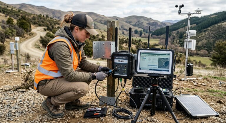
I’ve seen this scenario more times than I can count. A technician swears a load cell is faulty because the reading is erratic, and the real problem is a weak millivolt signal picking up interference on its way to the control room. Amplifying that signal close to the sensor, rather than at the far end, fixes it in one step.
XTRAN’s RM-044 signal conditioning unit is a good example of this in practice. It’s built specifically for strain gauge type transducers, with gain selectable from 120 to 3200 and a configurable output of ±10 V or 4-20 mA, designed to sit close to the sensor and do the amplifying before noise has a chance to creep in.
Filtering: Cutting Out the Noise
Amplification alone doesn’t help much if it just makes the noise louder along with the signal. That’s where filtering earns its keep.
Industrial sites are noisy places, electrically speaking. Variable speed drives, contactors, welding equipment, and long cable runs all inject unwanted frequencies into a measurement signal. A low-pass filter removes high-frequency noise while letting the genuine, slower-changing measurement through. A notch filter targets one specific frequency, such as the 50 Hz mains hum that turns up on almost every industrial site in Australia.
Get the filter cutoff wrong and there’s a trade-off either way. Set it too aggressively and real, fast-changing events, like a pressure spike or a shock load, get smoothed out along with the noise. Set it too loosely and the noise stays in the data. Getting that balance right depends on knowing what the sensor is actually measuring and how quickly that value genuinely changes.
Linearisation and Signal Conversion
Not every sensor produces a straight-line output. Thermocouples, for instance, have a distinctly non-linear relationship between voltage and temperature, and the curve shifts depending on which part of the range you’re in. Linearisation corrects for this during conditioning, so a downstream system doesn’t need to apply complex correction math to raw voltage readings.
Signal conversion is the other half of this stage: taking whatever native format the sensor produces and translating it into the standard the rest of the system speaks, whether that’s current loop to voltage, resistance to voltage, or frequency to analog. XTRAN’s RM-074 does exactly this for LVDTs, handling excitation, amplification and demodulation, then outputting a signal compatible with PLCs, computer input cards, and data loggers.
Analog-to-Digital Conversion: Bridging Sensor and System
Somewhere along the chain, an analog signal, whether a voltage, current, or resistance, has to become a digital number a computer can store, display, and act on. That’s the analog-to-digital converter’s job.
An ADC samples the analog signal at regular intervals and assigns each sample a digital value. Two things define how well it does this: resolution, meaning how many discrete steps it can represent, and sampling rate, meaning how often it takes a reading. A 12-bit ADC gives roughly 4,096 possible values across the input range; a 16-bit ADC gives 65,536. For a load cell measuring across a wide force range, that resolution gap decides whether small load changes actually register or get lost in rounding.
Sampling rate matters just as much, particularly for anything that changes quickly, such as vibration, impact events, or fast pressure transients. Sample too slowly and you’ll miss the peak of a short event entirely, even if the sensor itself captured it perfectly.
This is also usually where the last line of defence against electrical noise sits, since most modern signal conditioning modules and data loggers combine filtering and ADC on the same board.
Why All of This Matters for Measurement Accuracy
Here’s the part that catches people out: a sensor’s published accuracy specification assumes it’s connected to properly designed signal conditioning. A load cell rated to 0.03% accuracy will not deliver that number wired straight into a generic PLC input with no amplification, no filtering, and no allowance for cable length or electrical noise.
Every stage in the chain, amplification, filtering, linearisation, conversion, and ADC, either preserves the sensor’s real accuracy or erodes it. Get the amplification stage wrong and small readings get swallowed by noise. Get the filtering wrong and either the noise or the genuine signal disappears along with it. Get the ADC resolution too low and fine measurement changes never make it into the data at all.
This is why measurement problems that look like “the sensor’s faulty” are, more often than not, a conditioning problem instead. I’ve swapped out perfectly good pressure transducers on customer sites because nobody suspected the amplifier stage, only to have the exact same fault reappear on the replacement unit.
How XTRAN Pairs Signal Conditioning With Sensors
This is one of the reasons XTRAN doesn’t treat signal conditioning as a separate afterthought. Sensors, signal conditioning, and the rest of the measurement chain get specified together, so gain, filtering, and output format are matched to the actual sensor from the start rather than guessed at after installation.
For mining and defence applications specifically, that pairing matters even more. A sensor network deployed for mining or defence use has to survive vibration, temperature swings, and heavy electrical interference from nearby machinery, and the signal conditioning needs to be specified with those conditions in mind rather than assumed generic. XTRAN’s XTMS telemetry platform is built around this same idea: sensors, conditioning, wireless communication, and logging designed as one system rather than assembled from mismatched parts after the fact.
If you’re weighing up which industrial sensor actually fits your application, it’s worth asking the conditioning question at the same time as the sensor question. The two decisions aren’t really separate, and treating them that way is usually where accuracy problems start.
Frequently Asked Questions
- What’s the difference between a signal conditioner and an amplifier?
- Do all sensors need signal conditioning?
- Can poor signal conditioning cause a sensor to fail calibration checks?
- How do I know if measurement noise is coming from the sensor or the conditioning?
An amplifier only boosts signal strength. A signal conditioner is broader: it can amplify, filter, linearise, isolate, and convert a signal, often combining several of these functions in a single module such as XTRAN’s RM-044 or RM-074.
Most industrial sensors that output low-level analog signals, such as strain gauges, thermocouples, and LVDTs, need some form of conditioning. Sensors with a built-in digital output or integrated amplifier need less external conditioning, but rarely none at all.
Yes. A sensor can pass a bench calibration and still produce inaccurate readings in the field if the conditioning stage introduces noise, gain error, or an ADC bottleneck that wasn’t present during the original calibration.
Check the raw sensor output as close to the sensor as possible, before conditioning. If the noise is already present there, it’s likely an installation or wiring issue. If it appears further down the chain, the conditioning stage is the more likely cause.
Getting the Conditioning Right From the Start
Signal conditioning isn’t the exciting part of a measurement system, but it’s the part that decides whether the sensor you paid good money for actually delivers the accuracy printed on its datasheet. Amplification protects weak signals from noise. Filtering keeps the noise out without losing the real event. Analog-to-digital conversion decides how finely that signal ultimately gets recorded.
Get all three right, matched to the sensor and the environment it’s working in, and the rest of the measurement chain has a fighting chance of being accurate. Get any one of them wrong, and no amount of downstream calibration fully makes up for it.
If you’re specifying a new sensor network or troubleshooting accuracy problems on an existing one, talk to XTRAN’s team about matching sensors and signal conditioning to your application.
XTRAN
Phone: (03) 98745777
Email: info@xtran.com.au
Location: Unit 24 A/49 Corporate Blvd, Bayswater VIC 3153, Australia
Hours: Monday to Thursday 09:00 – 17:00 Friday 09:00 – 16:00